You're here: MiBSAR's home page :: SAR operations land navigation resource index page :: UTM coordinate system page
The Universal Transverse Mercator (UTM) geographic coordinate system
By
Michael A. Neiger
Marquette, Michigan
© Copyright 2010 - 2022
Thanks in advance for reporting any errors, inaccuracies, or missing information in this book to the author.
| Page index
|
Becoming proficient with the Universal Transverse Mercator (UTM) coordinate system — that is, learning to quickly and accurately calculate the UTM coordinates of a specific location on a topographic quadrangle (for input into a GPS unit) or plot UTM coordinates on a quadrangle (derived from a GPS unit) — is an essential wilderness skill. Mastery of the UTM coordinate system |
Top
Introduction to the UTM
coordinate system
The Universal Transverse Mercator coordinate system — or UTM, as it's commonly referred — is a international locational reference system that depicts the Earth's three-dimensional surface in a relatively-accurate, two-dimensional manner.
 | |
|
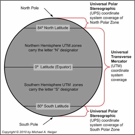
Global coverage of the Universal Transverse Mercator (UTM)
and Universal Polar Stereographic (UPS) coordinate systems. | |
The UTM coordinate system allows users to accurately and unambiguously identify geographical locations anywhere on the Earth's surface between the northern limits of North America (defined as 84 degrees north latitude) and the southern limits of continent of Antarctica (defined as 80 degrees south latitude).
The remaining north and south polar regions — those areas above 84 degrees north latitude and below 80 degrees south latitude, respectively — are not included in the UTM coordinate system due to extreme projection distortions in the UTM grid as compared to the meridians of longitude.
Instead, these two polar regions are covered by the Universal Polar Stereographic, or UPS, coordinate system.
Universal Polar Stereographic (UPS) coordinate system: According to the UPS coordinate system, the Northern Hemisphere's polar region extends from 84 degrees north latitude to the North Pole, which is located at 0 degrees north latitude. This region is split in half, with the Western Hemisphere creating Zone Y and the Eastern Hemisphere creating Zone Z.
The Southern Hemisphere's polar region extends from 80 degrees south latitude to the South Pole, which is located at 0 degrees south latitude. This region is split in half, with the Western Hemisphere creating Zone A and the Eastern Hemisphere creating Zone B.
To provide a small degree of overlap for those operating on the margins of both the UTM and UPS coordinate systems, the UPS system overlaps the UTM system by an additional 30 minutes of latitude.
Unlike the Latitude/Longitude coordinate system — or LAT/LON as it's often referred — which is a three-dimensional, angular-based, spherical coordinate system relying on the degree, minute, and second units of measure, the UTM coordinate system is a two-dimensional, plane-based, rectangular coordinate system relying on the meter unit of measure.
The grid for the UTM coordinate system consists of parallel-running vertical (easting) lines and parallel-running horizontal (northing) lines, each of which is spaced exactly 1,000 meters (1 kilometer or klick) apart, all of which combine to form a map-wide grid of 1,000-meter squares.
The overall arrangement of the UTM grid is based on the Cartesian coordinate system, which is a rectangular, two-dimensional (plane) system in which the abscissa X (horizontal east/west) axis is replaced by a northing grid line, and the ordinate Y (vertical north/south) axis is replaced by an easting grid line.
In addition, the coordinates are meter-based and positive — they do not include negative values. Since the X-Y origin point, or zero point, for each zone lies outside the zone, the origin points are called false origins, and the coordinates themselves are often referred to as false coordinates.
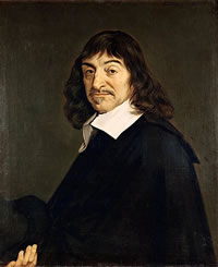
The Cartesian coordinate system was developed by René Descartes in 1637.
(Photo courtesy of Louvre Museum, Paris, France)René Descartes (1596-1650), was a celebrated French philosopher, mathematician, scientist, and writer. His Latin name was Renatus Cartesius.
Known as the father of modern, rationalistic philosophy, Descartes philosophy came to be called Cartesianism. His accomplishments included inventing co-ordinate or analytic geometry through the merging of algebra and geometry.
An opponent of Scholastic Aristotelianism, Descartes devoted himself to explaining man and the universe through the application of mathematics, logical reasoning, and experimentation. He became famous for the Latin axiom, cogito, ergo sum, which translates to "I think, therefore I am."
Descartes works included
- Discourse on the Method for Rightly Conducting Ones Reason, and Searching for Truth in the Sciences (1637; his most famous work), which became known as the Discourse on Method;
- Meditations on First Philosophy (1641; his principal philosophical work);
- and Principles of Philosophy (1644).
Top
Why use the UTM coordinate
system?
While the LAT/LON coordinate system is the first choice of pilots, sailors, and others using less-detailed, small-scale maps to navigate over great distances, seasoned wilderness trippers, expert search-and-rescue personnel, elite fighting units, professional orienteers, and others using highly-detailed, large-scale, topographic quadrangles for technical land navigation rely almost exclusively on the geospatial plane coordinate system known as the Universal Transverse Mercator (UTM) coordinate system (or, its close relative, the Military Grid Reference System [MGRS], in the case of military).
The UTM coordinate system has become the de facto standard coordinate system among expert land navigators for technical, wilderness operations for a number of reasons:
-
Every UTM grid is perfectly square and exactly the same size. All UTM coordinate grids are perfectly square and exactly the same size — 1,000 meters by 1,000 meters — across the entire grid system.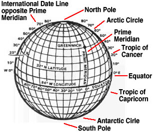 Unlike the Universal Transverse Mercator's (UTM) easting grid lines, which are always parallel to each other, the latitude/longitude coordinate system's meridians of longitude constantly taper as they near the polar regions. (Graphic adapted by Michael A. Neiger from the U.S. Army's Map Reading and Land Navigation Field Manual [FM 3-25.26, rev. 20 July 2001, formerly FM 21-26])
On the other hand, the angular-based, geographic LAT/LON coordinate grid is non-symmetrical and continually varying in both size and shape. This is due to the meridian of longitude lines — they form the left and right sides of each grid square — that curve towards each other as they depart the equator and converge at one or the other poles.For example, in the northern hemisphere, the width of one second of longitude varies from about 31 meters at the equator (0 degrees latitude); to about 3 meters at the northern limit of the UTM grid (84 degrees north latitude); to zero meters at the north pole (90 degrees latitude).
Because of this, most experienced wilderness land navigators prefer to use the intuitive and easy-to-use UTM coordinate system while underway in the bush as opposed to the slow and cumbersome LAT/LON coordinate system.
- UTM
coordinates are based on meters and the decimal system's units of ten. The
UTM coordinate system relies on the meter unit of measure, which incorporates
the simplicity of the decimal system and its easy-to-comprehend units of ten.
On the other hand, the LAT/LON coordinate system relies on the degree, minute, and second unit of measure, which incorporates the angular system and its cumbersome units of 60.
Because of this, most experienced wilderness land navigators find the UTM's decimal system, with its units of ten measure, much easier to comprehend and use while underway in the bush than the LAT/LON's angular system, with its units of 60.
- UTM
coordinates always have the same two directional designators and never carry negative
values. The
UTM coordinate system relies on positive-value-only coordinates, both of which
always carry the same two directional designators: east and north.
On the other hand, the LAT/LON coordinate system relies on angular coordinates that, depending on system parameters, can carry both positive and negative values, or two of four directional designators: east or west, and north or south.
Because of this, most experienced wilderness land navigators find the consistency of the UTM system's coordinates — no negative values and only east and north directional designators — much less prone to transpositional errors while underway in the bush, as compared to potential variability of the LAT/LON system's coordinates.
- The
UTM coordinate system is more accurate. The UTM coordinate system is more
accurate than the LAT/LON coordinate system when using whole units only (no decimal
places). For example, while the UTM coordinate system is accurate to one meter
at 45 degrees north latitude, the LAT/LON coordinate system is only accurate to
one second of latitude, or about 31 meters.
To achieve the accuracy of a whole-number-only UTM coordinate — one meter — two decimal places must be added to the LAT/LON coordinate system's seconds' designator, further complicating the field interpolative value of its angular data, which is based on units of 60, as opposed to the UTM's linear data, which is based on units of 10.
For sub-meter accuracy, professional-grade GPS units output UTM coordinate system data strings with one or more decimal places.
Because of this, most experienced wilderness land navigators find the linear UTM system and its whole-numbers-only, meter-based coordinates easier to use while underway in the bush than the angular LAT/LON system and its degrees, minutes, and seconds-based coordinates. 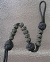 The
UTM coordinate system works seamlessly with US Army Ranger pacing beads. The
UTM coordinate system's 1,000-meter grid arrangement is optimized for seamless
use with the US Army Ranger pacing system's 100-meter and 1,000-meter beads, unlike
the angular-based grid of the LAT/LON coordinate system.
The
UTM coordinate system works seamlessly with US Army Ranger pacing beads. The
UTM coordinate system's 1,000-meter grid arrangement is optimized for seamless
use with the US Army Ranger pacing system's 100-meter and 1,000-meter beads, unlike
the angular-based grid of the LAT/LON coordinate system.
Because of this, most experienced wilderness land navigators find US Army Ranger pacing beads easier to use with the UTM coordinate system, as opposed to the LAT/LON coordinate system, while underway in the bush.
- Field-expedient
UTM plotters are easy to improvise. Field-expedient coordinate plotters are
a snap to improvise in the bush for use with the UTM grid system. On the other
hand, creating an accurate, easy-to-use, coordinate plotter for use with the LAT/LON
grid is a much more involved and complicated process.
Because of this, most experienced wilderness land navigators find it much easier to fabricate field-expedient plotters for the UTM coordinate system while underway in the bush than plotters for the LAT/LON coordinate system.
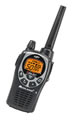 UTM
coordinate system data strings are easier to transmit electronically. With
no degree, minute, or second designators interspersed among their data strings,
and no one-, two-, or three-digit-value variability among their data strings,
and no format-selection variability, UTM coordinates are much easier and faster
to transmit electronically than LAT/LON coordinates.
UTM
coordinate system data strings are easier to transmit electronically. With
no degree, minute, or second designators interspersed among their data strings,
and no one-, two-, or three-digit-value variability among their data strings,
and no format-selection variability, UTM coordinates are much easier and faster
to transmit electronically than LAT/LON coordinates.
Because of this, most experienced wilderness land navigators find UTM coordinate system data strings much easier to transmit electronically while underway in the bush than LAT/LON coordinate data strings.
-
UTM coordinate system data strings are easier to shorten. UTM coordinate system data strings can be easily shortened or collapsed when less precision is needed by simply dropping the single meter designators, ten-meter digit designators, hundred-meter designators, etc., from both the easting and northing coordinates.
Because of this, most experienced wilderness land navigators find UTM coordinate system data strings much easier to shorten while underway in the bush than LAT/LON coordinate data strings.
- UTM grid lines make distance
and area calculations a snap. With its symmetrical, unchanging, 1,000-meter-based
grid lines, the UTM coordinate grid lends itself to rapid geometric calculations,
particularly those involving distance and area.
Because of this, most experienced wilderness land navigators find the UTM system's easting and northing lines much easier to use for distance determination or area calculations while underway in the bush than the LAT/LON system's meridians of longitude and parallels of latitude.
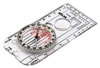 UTM
easting grid lines make azimuth calculating and plotting a snap. The one-klick
(kilometer) interval spacing of the UTM coordinate system's easting grid lines
make them much more convenient for calculating and plotting azimuths with a base-plate
compass than the widely-and-inconveniently-spaced LAT/LON system's meridian of
longitude lines, which, in Michigan, have an interval spacing of nearly three
klicks.
UTM
easting grid lines make azimuth calculating and plotting a snap. The one-klick
(kilometer) interval spacing of the UTM coordinate system's easting grid lines
make them much more convenient for calculating and plotting azimuths with a base-plate
compass than the widely-and-inconveniently-spaced LAT/LON system's meridian of
longitude lines, which, in Michigan, have an interval spacing of nearly three
klicks. Because of this, most experienced wilderness land navigators find the UTM system's easting grid lines much easier to use for calculating and plotting azimuths with a base-plate compass while underway in the bush than the LAT/LON system's meridian of longitude lines.
For these reasons and more, the UTM coordinate system has become the primary coordinate grid overlaid on most modern, large-scale, topographic quadrangles in the US and Canada. And the ease, speed, and accuracy with which it can be used while underway in the bush has made the UTM coordinate system the hands-down favorite among experienced wilderness land navigators.
Top
History of the UTM coordinate
system


 Developed
by the US Army Map Service in the late 1940s — probably 1947 — and shortly
thereafter adopted by US Army
Developed
by the US Army Map Service in the late 1940s — probably 1947 — and shortly
thereafter adopted by US Army
as well as North Atlantic Treaty Organization (NATO)
forces, the Universal Transverse Coordinate (UTM) projection and grid system remained
a classified secret for many years.
Still in use today, the civilian version retains the UTM coordinate system name while the military version carries the Military Grid Reference System (MGRS) coordinate system name.
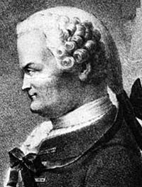
The UTM grid system is a relatively simple and intuitive, plane, rectangular grid system based on an adaptation of the ellipsoidal Transverse Mercator map projection developed by Johann Lambert in 1772 — and sometimes referred to as the Gauss-Kruger projection, particularly in Europe — that includes central meridians.
Johann Heinrich Lambert (1728-1777) was a noted Swiss-German physicist, mathematician, astronomer, philosopher, and cartographer who is credited with developing several map projections in 1772, including the cylindrical, equal-area projection known as the Lambert cylindrical equal-area projection, or Lambert cylindrical projection.
Born the son of a poor tailor, this self-taught genius is best remembered for rigorously proving that e and pi were irrational; for his work in color, light, and heat, including developing a method of calculating light absorption and intensity, known as the lambert unit of brightness, and formulation of a color pyramid; developing a theorem on planet motion; calculating the coefficient of air expansion; and developing the trigonometric concept of hyperbolic functions.
Several laws carry his name, including Lambert's cosine law and Lambert's law of absorption. His final eight years of life were spent as a protégé of Frederick the Great (Frederick II of Prussia).
His dozens of treatises include such notable ones as:
- Photometria (1760),
- Cosmologische Briefe über die Einrichtung des Weltbaues (1761),
- Neues Organon (1764),
- DieTheorie der Parallelinien (1766),
- Zusatze zu den logarithmisch-trigonometrischen Tabellen (1770),
- Anlage zur Architectonic (1771)
- Freie Perspective (1774),
- Pyrometrie (1779),
- Deutscher Gelehrter Briefwechsel (1781-1784),
- and Opera mathematica (1946).
The transverse in a transverse Mercator map projection comes from the fact the map strips run vertically, from pole to pole, as opposed to horizontally, parallel to the equator, as in a standard Mercator map projection.
 |
|
The Mercator map projection. (Graphic courtesy of the United States Geological
Survey) |
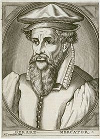
The standard Mercator map projection — upon which the transverse Mercator is based — was developed by Gerardus Mercator in 1569.
His revolutionary maps used the Mercator projection — a technique named after him — to represent the Earth's three-dimensional, sphere-shaped surface on two-dimensional paper.
The Mercator projection used the cylindrical projection method in which both parallels and meridians were represented as straight lines. The problem with this projection was the extreme distortion as the map neared the poles since the meridians of longitude did not converge at the poles but continued straight north. This groundbreaking discovery allowed navigators to calculate both distance and direction from their maps.
(Photo courtesy of National Maritime Museum, Greenwich, London)Gerhardus Mercator (1512-1594), or Gerardus or Gerard (his given name was Gerhard or Gerard De Cremer [or Kremer], but he chose to use his Latin name), was a celebrated Flemish cartographer, court cosmographer (geographer), calligrapher, mathematician, talented scientific-instrument maker, professor, engraver, and surveyor who is credited with creating the first modern, 18-sheet world map in 1569 — the Nova et aucta orbis terrae descripto ad usum navigantium emendate accommodata (1569) — using his Mercator projection technique.
The son of a farmer and cobbler, Mercator received a masters degree from the University of Louvain in Louvain, Belgium. In addition to his map of the world, one of most influential works was the Atlas, or Cosmographical Meditations on the Structure of the World (1595), the first modern atlas (a term he invented for a work envisioned to explain the creation of the world as well as lay out its complete history).
He also published a number of other notable maps and charts, constructed celestial and terrestrial globes, created a thorough guide to italic lettering, and wrote On the Use of the Astronomical Ring, Chronologia (1569) and Tabulae Geographicae (1578-1584).
| The
transverse Mercator map projection. |
The conformal transverse projection used in the UTM coordinate system — which cartographers use to portray spherical, Earth-based geographical data in a plane-like map format with a reasonable degree of accuracy with regard to distance, direction, shape, and area — can be visualized by imagining turning a cylinder sideways and sliding a globe inside it, with the cylinder's axis parallel to, as well as on the same plane as, the globe's equator.
The UTM system is based not on a single map projection, but 60 projections. Each projection of the Earth — which consists of a narrow, south-to-north running band or wedding-ring-like swath, called a zone — allows it to be depicted in a relatively distortion-free manner (accurate to within 1 meter over 2,500 meters), unlike maps using the original equatorial Mercator projection (imagine removing and flattening a label from a soup can) that become increasingly distorted as they move away from the equator, toward the poles.
Each one of the 60 vertical grid zones discussed in the UTM vertical grid zones section below is represented by a band around the cylinder, with the central meridian of each band-turned-zone being the only area within the band that remains in contact with the underlying globe.
Top
UTM grid coordinate data
strings
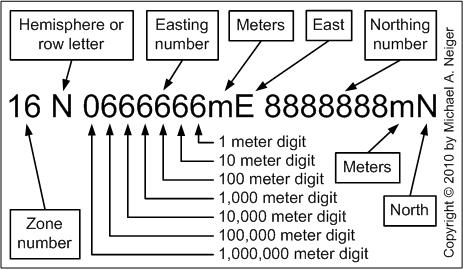 |
| The component parts
of a UTM grid coordinate data string. (Graphic by Michael A. Neiger) |
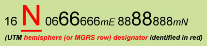
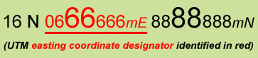
UTM grid coordinate data strings should always be written or conveyed in a Z-E-N format (Zone-Easting-Northing); that is, with the zone number listed first; the six-digit data string representing the easting designator second; and the seven-digit (six digits near the equator) data string representing the northing designator third.
Likewise, many protocols will include a hemisphere letter (or horizontal row) designator between the zone number and the six-digit easting designator.
It should be noted that according to some protocols, a leading zero will be added to the six-digit easting data string to make it match the northing data string, digit-wise, especially when both coordinates are collapsed together for certain purposes. This makes it very easy to split a single data string in half, and reveal the individual easting and northing coordinates.
Top
UTM vertical grid zones
 The
UTM coordinate system depicts the Earth's three-dimensional surface as a perfectly-flat,
two-dimensional plane by dividing its surface into 60, equally-spaced, vertically-arranged
planes known as zones, or world zones.
The
UTM coordinate system depicts the Earth's three-dimensional surface as a perfectly-flat,
two-dimensional plane by dividing its surface into 60, equally-spaced, vertically-arranged
planes known as zones, or world zones.
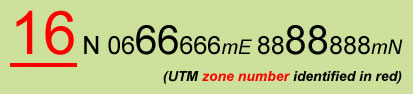
In the UTM coordinate data string shown at the right, the zone number — 16 — is represented by the first two digits.
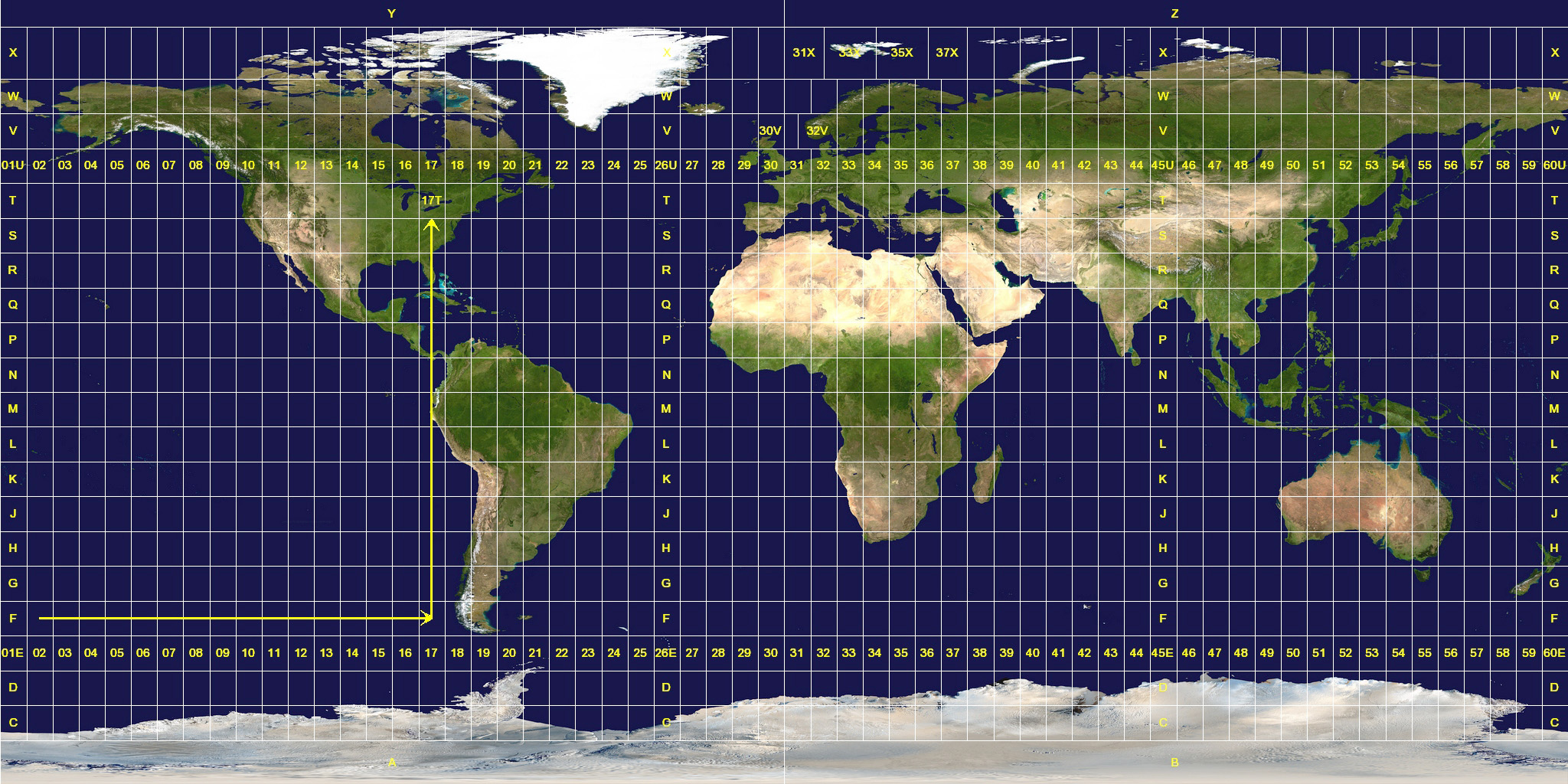 |
| The
sixty grid zones of the Universal Transverse Mercator (UTM) coordinate system — depicted
by the vertical columns labeled 1 through 60 in the above image — cover the
entire world, save the northern and southern polar regions, which are covered
by the Universal Polar Stereographic (UPS) coordinate system. Click
here or on graphic to view high-resolution imagery of the UTM world zone map. (Graphic courtesy of Jan Krymmel via Wiki) |
Known as gores in terrestrial globe-speak, the shape of the nearly-pole-to-pole-running UTM meridional zones is not unlike the outer surface of a partitioned section of an orange that has been peeled back and flattened.
World UTM zones. Sequentially-numbered 1 through 60, from west to east, the zero or starting point for the zones (and the common border between Zone 1 and Zone 60) is the 180-degree east (or west) meridian of longitude.
Located in the Pacific Ocean, the 180th meridian, or International Date Line, is situated directly opposite the zero-degree meridian of longitude, or Prime Meridian — which runs through Greenwich, a borough in London England — that forms the common border between Zone 30 and Zone 31.
In other words, Zone 1 encompasses the area between 180 degrees west longitude (the International Date Line) and 174 degrees west longitude; Zone 2 encompass the area between 174 degrees west longitude and 168 degrees west longitude; and so forth, until Zone 60, which encompasses the area between 174 degrees east longitude and 180 degrees east longitude (the International Date Line).
 |
| Zones
10 through 19 of the Universal Transverse Mercator (UTM) coordinate system cover
the contiguous United States. The State of Michigan is covered by Zones 15 through
17 cover . (Graphic adapted by Michael A. Neiger from base imagery courtesy of
the United States Geological Survey [USGS]) |
US UTM zones. The contiguous United States — the 48 conterminous states — situated between 66 degrees west longitude and 126 degrees west longitude — a 60-degree swath of longitude — is covered by 10 UTM zones, beginning with Zone 10 on the west coast, covering northern California, Oregon, and Washington, and ending with Zone 19 on east coast, covering Maine and Rhode Island as well as portions of Vermont, New Hampshire, Massachusetts, Connecticut, and New York.
Michigan UTM zones. The State of Michigan, situated between 82 degrees west longitude and 91 degrees west longitude — a 9-degree span of longitude — is covered by 3 zones, beginning with Zone 15 at the extreme, western side of the Upper Peninsula and ending with Zone 17 on the extreme, eastern side of the state.
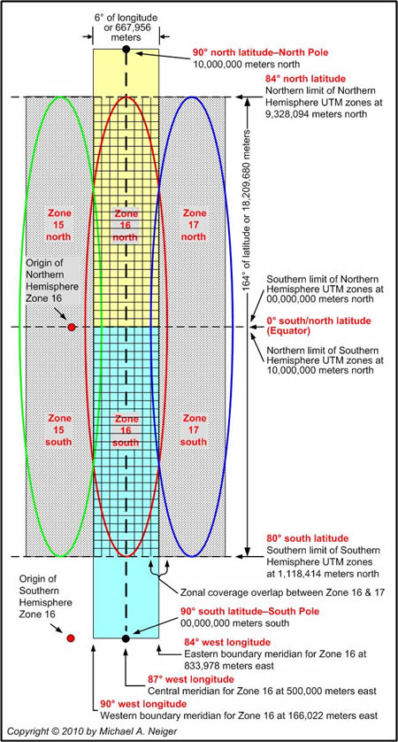 |
| Zone 16 in the Universal Transverse
Mercator (UTM) coordinate system. (Graphic by Michael A. Neiger) |
Zonal width. The width of a UTM zones varies according to longitudinal position.
At the equator (0 degrees north [or south] latitude) — the widest point in a six-degree zone — a zone spans about 667,956 meters (668 kilometers, or 401 miles), with minimum and maximum easting coordinate values of 166,022 and 833978 meters, respectively, not including 30-minutes of overlap on each side.
Zonal overlap. To permit relatively-seamless use of the UTM coordinate system while operating near zonal boundaries, each zone includes an additional 30 minutes — or about 55,702 meters — of coverage beyond its eastern and western bounding meridians at the equator.
At the 84th parallel of north latitude, the northern limit of the UTM coordinate system, a zone spans about 70,020 meters (70 kilometers or 42 miles) of longitude.
At the 80th parallel of south latitude, the southern limit of the UTM coordinate system, a zone spans about 116,310 meters (116 kilometers or 70 miles) of longitude.
Zonal length. Each UTM zone covers the region between 80 degrees south latitude and 84 degrees north latitude, a 164 degree span of latitude.
Along their central meridians, UTM zones measure about 18,209,680 meters in length.
Each zone is divided in half at the equator (0 degrees north [or south] latitude) — according to hemisphere — which effectively creates 120 separate UTM coordinate zones.
Due to extreme distortion in the southern and northern polar regions of each UTM zone, the Earth's surface below 80 degrees south latitude and above 84 degrees north latitude is covered by the Universal Polar Stereographic (UPS) coordinate system.
Zonal meridians and parallels. Each zone has three important meridians of longitude and one important parallel of latitude.
Longitudinally, each 6-degree-wide UTM zone is split in half, bisected vertically by a transverse mercator projection line, which is variously known as a zone meridian, central meridian, or longitude of origin. Each zone is also bounded on each side — to the west and east — by a meridian of longitude, or bounding meridian.
The geodetically-true zone meridian is the only easting grid line within the zone that cuts the equator in a perpendicular fashion while at the same time connecting the north and south poles. In addition to serving as a zone's origin — for calibrating its easting coordinates — all of the zone's UTM easting grid lines are arrayed parallel to this all-important central meridian.
All other meridians (or lines of longitude) in a particular zone — other than the zone meridian (or central meridian) — are slightly distorted to one degree or another from their true form since the zone, originally a 3-dimensional representation of a slice of the Earth's surface, was flattened into a two-dimensional plane so a grid of easting and northing lines could be superimposed on it.
Geometric distortion note: To reduce geometric distortion across a zone, the scale of the zone meridian (central meridian) is intentionally reduced by a factor of 0.9996. This nominal, 0.0004 percent reduction in scale of the central meridian creates parallel lines with zero distortion at points 180,000 meters to the west and east of the meridian.
Each UTM zone also has a central parallel, which is located on the equator. All northing grid lines are arrayed parallel to the equatorial parallel.
As the only easting and northing grid lines truly aligned with a meridian of longitude and a parallel of latitude in a UTM zone, the central meridian and central parallel are what tie the UTM coordinate system to the geographic latitude/longitude coordinate system.
Zonal origin. To eliminate the need for — and the resulting confusion of — negative numbers in the UTM coordinate system, each zone's west-to-east (left-to-right) measuring system uses a false origin, a zero point that lays well outside of the bottom of the zone's western boundary meridian.
This is accomplished by arbitrarily assigning the easting grid line coinciding with a zone's central meridian the value of 500,000 meters. In other words, at the equator, the westernmost easting line in a zone does not carry a value of zero, but a value of 166,022 meters. The zone's actual zero point of origin ends up being an imaginary line well outside and west of the zone's western limit.
Tip. Keeping this rule in mind, any easting value of less than 500,000 meters lays west (or to the left) of a zone's central meridian, and any easting value greater than 500,000 meters lays east (or to the right) of it.
With the point of origin located well outside of a UTM zone's western meridian, zonal origins and coordinates are often referred to as false origins and false coordinates, respectively.
Grid north. Only the easting grid line coinciding with a UTM zone's central meridian — which has a value of 500,000 meters — will be aligned with true north.
Due to the distortion inherent in representing a three-dimensional surface in a two-dimensional manner, no other easting grid lines in a UTM zone will be aligned with true north and have a convergence angle of 0°00' from true north.
Easting grid lines lying west of a UTM zone's central meridian — those with a value less than 500,000 meters — will have a westerly grid declination offset (or convergence angle) from true north, increasing to just over two degrees west near the zone's western boundary meridian.
Easting grid lines lying east of a UTM zone's central meridian — those with a value greater than 500,000 meters — will have a easterly grid declination offset (or convergence angle) from true north, increasing to just over two degrees east near the zone's eastern boundary meridian.
Most maps list a UTM zone's convergence angle in the margin of the quadrangle. Commonly referred to as grid north, this angle is specified in minutes and degrees, either graphically or textually.
Top
UTM horizontal grid hemispheres
(or rows)
 In
the UTM coordinate data string shown at the right, the zone hemisphere letter — N — follows
the zone number 16.
In
the UTM coordinate data string shown at the right, the zone hemisphere letter — N — follows
the zone number 16.
By convention, the civilian UTM coordinate system splits each zone in half, horizontally, at the equator, which effectively creates northern hemisphere zones and southern hemisphere zones.
Consequently, each UTM coordinate system data string carries a hemisphere designator indicating whether it is located in the southern or northern hemisphere.
Grid hemisphere designator letters
 | |
|
The equator (0 degrees latitude) splits the zones of the Universal
Transverse Mercator (UTM) system in half, with those located in the Northern Hemisphere
carrying the "N" designator and those located in the Southern Hemisphere
carrying the "S" designator. (Graphic by Michael A. Neiger) | |
By convention, civilian UTM coordinate system data strings situated north of the equator carry a hemisphere designator of "N" while those situated south of the equator carry a hemisphere designator of "S."
Notice to users of GPS units and digital mapping programs.
Most modern global positioning system (GPS) units and digital mapping software products are not programmed to report out UTM coordinate system data strings with the simple "N" or "S" hemispherical designators.
Instead, most modern GPS units and mapping programs report out hemisphere data according to the conventions of the alphanumeric, military version of the UTM coordinate system — the military grid reference system (MGRS) — which orders coordinate data strings according to where they fall within 60, six-degree-wide vertical zones, and 20, eight-degree-wide horizontal rows (one of which, the northern-most, is 12 degrees wide). Ten of the rows are located in the northern hemisphere and 10 are located in the southern hemisphere.
The MGRS coordinate system uses alphanumeric data strings for two reasons — they allow for shorter data strings, and they reduce communication errors since letters can be "spelled out" phonetically when broadcast (Alpha for A, Bravo for B, Charlie for C, etc.).
MGRS grid row designators
|
| The
60 grid rows labeled C through H, J through N, and P through X of the Universal
Transverse Mercator (UTM) coordinate system — depicted by the lettered, horizontal
rows in the above image — cover the entire world, save the northern and southern
polar regions, which are covered by the Universal Polar Stereographic (UPS) coordinate
system. Click here or on graphic
to view high-resolution imagery of the UTM world row map. (Graphic courtesy of Jan Krymmel via Wiki) |
The military version of the UTM coordinate system — the military grid reference system (MGRS) — divides the non-polar regions of the Earth into 20 equally-spaced, horizontally-running (west-to-east) rows.
Completely encircling the Earth, each row is exactly 6 degrees wide — except for the 12-degree-wide, northernmost row situated between 72 degrees north latitude and 84 degrees north latitude. MGRS rows have also been referred to as "latitudinal parcels" and "latitude bands."
The individual, rectangular grid squares formed by the intersection of a zone and a row cover a 100,000-meter area.
The shape of these International Date Line-to-International Date Line-running UTM rows are not unlike thin, crosswise slices of an onion.
Lettered C through X from south to north — with the exception of I and O, which were omitted to avoid any confusion with the numbers one and zero — the zero point for the rows is the 80-degree south parallel of latitude, which is situated 13.5 degrees of latitude north of the Antarctic Circle.
For example, the first row, Row C, would encompass the area between 80 degrees south longitude and 72 degrees south longitude; Row D would encompass the area between 72 degrees south longitude and 64 degrees south longitude; and so forth.
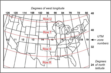 |
| Rows R, S,
T, and U of the Military Grid Reference System (MGRS) cover the contiguous United
States. Rows T and U cover the State of Michigan. (Graphic adapted by Michael A. Neiger from base imagery courtesy of the United States Geological Survey [USGS]) |
US grid row designators. The contiguous United States, situated between 24 degrees north latitude and 49 degrees north latitude — a 25-degree swath of latitude — is covered by 4 rows, starting with Row R on the southern border, covering all of Florida as well as portions of Texas, Louisiana, Mississippi, Alabama, and Georgia, and ending with Row U on the northern border, covering parts of Washington, Idaho, Montana, North Dakota, Minnesota, and Michigan.
Michigan grid row designators. The state of Michigan, situated between the 41 degrees north latitude and 49 degrees north latitude — an 8-degree-wide swath of latitude — is covered by 2 rows, starting with Row T covering the vast majority of the state north of its southern border, and ending with Row U covering a tiny portion of the northeastern tip of Isle Royale in northern Lake Superior.
Points of confusion
It should be noted that some purveyors of UTM coordinate system data strings do not include a hemisphere (or row) designator embedded between the zone designator and the easting coordinate since it's assumed those using the coordinates at hand will known whether they are working north or south of the equator.
As such, users of the civilian UTM coordinate system must remember that a UTM coordinate data string lacking hemispherical data can in fact represent two locations simultaneously: one in the northern hemisphere and one in the southern hemisphere.
If a civilian UTM coordinate data string includes a MGRS row designator following the Zone designator, knowing which row designators are assigned to which hemisphere will allow one to determine the hemisphere the UTM coordinate data string is located in:
Southern hemisphere UTM row designators: C, D, E, F, G, H, J, K, L, and M
Northern hemisphere UTM row designators: N, P, Q, R, S, T, U, V, W, and XTip: Any zone designator of N or higher represents a zone in the Northern Hemisphere.
Users of civilian UTM coordinate system data strings should use caution when working with data strings that include a zone designator followed by either the letter "N" or "S" since the designators could represent two locations, depending on whether the letters are referring to hemisphere or row.
For example, in civilian UTM coordinate system data strings adhering to the original conventions of the civilian UTM coordinate system, the letter "S" following the zone designator would indicate the data string is located in the "S"outhern Hemisphere. On the other hand, with many modern GPS units and digital mapping programs outputting UTM coordinate system data strings with hemispherical data according to the conventions of the military grid reference system (MGRS), the letter "S" following the zone designator would indicate the data string is located in the narrow, 6-degree-wide row situated near the latitudinal midpoint of the Northern Hemisphere, not in the southern hemisphere.
Similarly, in civilian UTM coordinate system data strings adhering to the original conventions of the civilian UTM coordinate system, the letter "N" following the zone designator would indicate the data string is located in the "N"orthern Hemisphere. On the other hand, if the UTM coordinate system data string follows the conventions of the military grid reference system (MGRS), the letter "N" would indicate the data string is located in the narrow, 8-degree-wide row situated immediately north of the equator.
Top
UTM easting coordinates
 The
UTM easting coordinate data string represents a position's location in meters,
east the grid's false origin, which is always located to the west, or left of
the position.
The
UTM easting coordinate data string represents a position's location in meters,
east the grid's false origin, which is always located to the west, or left of
the position.
UTM grid coordinates are always written or conveyed with the easting data string appearing first, before the northing data string.
The meter. In 1791, the French Academy of Sciences established a universal system of measurement with a single unit of length based on nature.
A meter is one-tenmillionth of one-quarter of the earth's circumference, as measured along the Prime Meridian, between the equator and the North Pole.
(Graphic courtesy of Scientific American Reference Book — A Manual for the Office, Household and Shop, by Albert A. Hopkins and A. Russell Bond (1905, Munn & Company)
Known as the metre — and derived from the word metron, the Greek term for "a measure" — it was initially defined as equal to one ten-millionth of the circumference of an Earth's quadrant, as measured between the equator and the North Pole, along the Prime Meridian, or the zero degree line of longitude passing through Paris, France.
|
By common convention, easting coordinate data strings output from GPS units are typically followed by the letter "E," meaning "east."
On digital and hardcopy quadrangles, the full easting coordinate data strings appearing along the neat lines in the top and bottom margins are usually followed by the letters "mE," meaning "meters east."
Since easting coordinates increase in value from a zone's western boundary to the zone's eastern boundary, easting grid coordinates are always read across, from left to right (or west to east) on quadrangles.
The starting value of a zone's western boundary varies depending on how far west it is from the zone's central meridian, which always assumes the false value of 500,000 meters.
The farther positions are located north of the equator (or south of the equator), the higher the numerical starting value of their respective western boundary.
Zone
16 in the Universal Transverse Mercator (UTM) coordinate system, showing the western
and eastern zone boundaries corresponding to the zone's western and eastern boundary
meridians at the equator.
(Graphic by Michael A. Neiger)
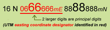 The
two larger-font digits in an easting coordinate along a quadrangle's marginal
neat lines are called principal digit numbers, and they identify the corresponding
1,000-meter UTM easting grid tick mark, and grid line if the quadrangle is overlaid
with UTM grid lines.
The
two larger-font digits in an easting coordinate along a quadrangle's marginal
neat lines are called principal digit numbers, and they identify the corresponding
1,000-meter UTM easting grid tick mark, and grid line if the quadrangle is overlaid
with UTM grid lines.
On USGS 1:24,000-scale quadrangles, the easting coordinate data strings adjacent to each light-blue tick mark just outside the map's top and bottom margin neat lines (and easting grid line if the quad is overlaid with UTM grid lines) are commonly shortened. To avoid clutter, the last three trailing digits are dropped — leaving just the 1,000-meter grid value — for all but one tick mark or grid line per map margin.
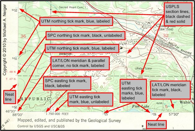
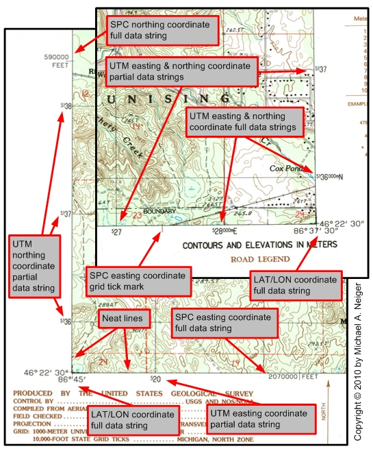 |
| A USGS 1:24,000-scale quadrangle
showing the neat lines and marginal data strings and tick marks in the bottom
left and bottom right corners for the Universal Transverse Mercator (UTM), Latitude/Longitude
(LAT/LON), and State Plane Coordinate (SPC) coordinate systems. (Graphic by Michael A. Neiger) |
In other words, the full easting coordinate data string — carried out to the nearest meter — appears only once per margin: once near the left side of the top margin (northwest corner of quad), and once near the right side of the bottom margin (southeast corner of quad).
In addition, full and partial easting coordinate data strings are printed in bold with all but the two principal digits in smaller, superscripted type.
Keep in mind map margin neat lines often bear coordinate data strings and their corresponding grid tick marks for two other coordinate systems: the latitude/longitude (LAT/LON) coordinate system and the state plane coordinate (SPC) system.
The 2.5-minute-interval latitude/longitude coordinate system is represented by short, black, tick marks adjacent to the inside of a map's neat lines, with full data strings appearing at all four corners. The 10,000-foot-interval state plane coordinate system is represented by short, black, tick marks adjacent to the outside of the map's neat lines, with full data strings appearing relatively near to the lower left and upper right corners of the map.
Note: While easting coordinate data strings are normally only six digits in length, convention often adds a leading zero to make them seven digits long so they correspond lengthwise with seven-digit northing coordinates, which reduces confusion, particularly when data strings are merged or shortened.
Top
UTM northing coordinates
 The
UTM northing coordinate data string represents a position's location in meters
north of the grid's false origin, which is always located to the south, or below
the position.
The
UTM northing coordinate data string represents a position's location in meters
north of the grid's false origin, which is always located to the south, or below
the position.
UTM grid coordinates are always written or conveyed with the northing data string following the easting data string.
|
By common convention, northing coordinate data strings output from GPS units are typically followed by the letter "N," meaning "north."
On digital and hardcopy quadrangles, the full northing coordinate data strings appearing along the neat lines in the left and right margins are usually followed by the letters "mN," meaning "meters north."
Since northing coordinates increase in value from a zone's southern boundary to the zone's northern boundary, northing grid coordinates are always read upward, from bottom to top (or south to north) on quadrangles.
In the northern hemisphere, a zone's southern boundary (and point of origin) is the equator, or 0 degrees north latitude, and it assumes the value of zero meters. A zone's northern boundary is located at 84 degrees north and it assumes the value of 9,328,094 meters, with the north pole assuming the value of 10,000,000 meters.
Zone 16 in the Universal Transverse Mercator (UTM) coordinate system, showing the equator serving as both the southern boundary for the northern hemisphere and the northern boundary for the southern hemisphere.
The
80 degree line of south latitude serves as the southern boundary for zones in
the southern hemisphere and the 84 degree line of north latitude serves as the
northern boundary for zones in the northern hemisphere.
(Graphic by Michael
A. Neiger)
In the southern hemisphere, a zone's southern boundary is the 80 degree line of south latitude, and it assumes a value of 1,118,414 meters. The south pole, at 90 degrees south latitude, assumes the value of zero meters and serves as the zone's point of origin, making it truly a false origin. The zone's northern boundary is located at the equator, or zero degrees south latitude, and it assumes a value of 10,000,000 meters.
While having separate origins for zones in each hemisphere eliminates the need for confusing negative numbers, a hemisphere (or row) indicator should always accompany UTM coordinate system data strings for clarity.
Note: Since all zones in both hemispheres share the equator as either a southern or northern boundary — 0 degrees south latitude or 0 degrees north latitude, respectively — positions located on the equator can have two different UTM northing grid coordinates, depending on whether the user is working in the southern or northern hemisphere.
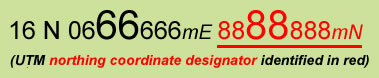
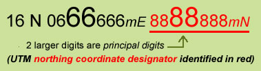 The
two larger-font digits in northing coordinates along a quadrangle's marginal neat
lines are called principal digit numbers, and they identify the corresponding
1,000-meter UTM northing grid tick mark, and grid line if the quadrangle is overlaid
with UTM grid lines.
The
two larger-font digits in northing coordinates along a quadrangle's marginal neat
lines are called principal digit numbers, and they identify the corresponding
1,000-meter UTM northing grid tick mark, and grid line if the quadrangle is overlaid
with UTM grid lines.
On USGS 1:24,000-scale quadrangles, the northing coordinate data strings adjacent to each light-blue tick mark just outside the map's left and right marginal neat lines (and northing grid lines if the quad is overlaid with UTM grid lines) are commonly shortened. To avoid clutter, the last three trailing digits are dropped — leaving just the 1,000-meter grid value — for all but one tick mark or grid line per map margin.
|
| A USGS 1:24,000 quadrangle showing
the neat lines and marginal coordinate system data strings and tick marks in the
bottom left and bottom right corners for the Universal Transverse Mercator (UTM),
Latitude/Longitude (LAT/LON), and State Plane Coordinate (SPC) coordinate systems. (Graphic by Michael A. Neiger) |
In other words, the full northing coordinate data string — carried out to the nearest meter — appears only once per margin: once near the top of the left margin (northwest corner of quad), and once near the bottom of the right margin (southeast corner of quad).
In addition, full and partial easting coordinate data strings are printed in bold with all but the two principal digits in smaller, superscripted type.
Keep in mind map margin neat lines often bear coordinate data strings and their corresponding grid tick marks for two other coordinate systems: the latitude/longitude (LAT/LON) coordinate system and the state plane coordinate (SPC) system .
The 2.5-minute-interval latitude/longitude coordinate system is represented by short, black, tick marks adjacent to the inside of the map's neat lines, with full data strings appearing at all four corners. The 10,000-foot-interval state plane coordinate system is represented by short, black, tick marks adjacent to the outside of the map's neat lines, with full data strings appearing relatively near to the lower left and upper right corners of the map.
Top
Drawing UTM grid lines on
maps
 To
use the UTM grid coordinate system with a quadrangle, it must be overlaid with
the UTM grid.
To
use the UTM grid coordinate system with a quadrangle, it must be overlaid with
the UTM grid.
Most newer maps — including 1:20,000-scale Ontario Base Maps, 1:50,000-scale Canadian topographic maps, and post-1982 1:24,000-scale USGS topographic maps have the UTM coordinate system grid superimposed on them in black.
USGS 1:24,000-scale maps published between about 1959 and 1982 are not overlaid with the UTM grid.
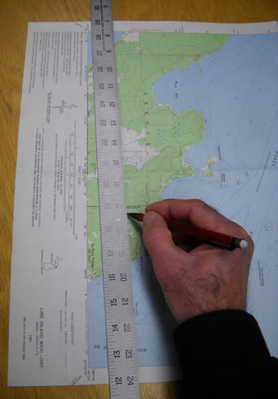
Pre-1982,
1:24,000 (7.5-minute), USGS quadrangles will likely need to have the UTM coordinate
system's grid lines drawn atop them before they can be used with UTM coordinate
system in the bush.
(Photo by Michael A. Neiger)
However, these pre-1982 quads have short, light-blue, tick marks and black numerical labels along the outside edge of the neat lines — the meridians of longitude and parallels of latitude framing the quad — that can be used to hand-draw the UTM grid lines atop the map.
Spaced at one-kilometer (or 1,000-meter) intervals, the light-blue tick marks along the top and bottom, as well as the left and right sides, of a quad correspond to the UTM coordinate system's easting and northing grid lines, respectively.
It should be noted that individual tick marks conflicting — space-wise — with marginal information may be left off, but they can be accurately plotted by simply using the kilometer scale along the map's collar to locate them relative to adjacent tick marks.
Be careful to avoid confusing tick marks from two other coordinate systems — the latitude/longitude (LAT/LON) coordinate system and the state plane coordinate (SPC) system — with those of the UTM coordinate system.
LAT/LON tick marks: The short, black, tick marks situated adjacent to the inside of a quad's neat lines correspond with the 2.5-minute-interval latitude/longitude coordinate system. With the 2.5-minute meridian grid lines spaced just over 3 kilometers apart, and the 2.5-minute parallel grid lines spaced at just over 4.5 kilometers apart, the LAT/LON grid divides the map into nine grid rectangles.
SPC tick marks: The short, black, tick marks situated adjacent to the outside of a quad's neat lines correspond with the 10,000-foot-interval state plane coordinate system. With the easting and northing grid lines spaced about three kilometers apart, the SPC grid divides the map into approximately 15 grid squares.
On a smooth, flat surface, use a long ruler — at least 24 inches in length for 7.5-minute USGS quads — and a very sharp pencil to connect the UTM coordinate system's corresponding pairs of light-blue grid tick marks, which are located adjacent to the outside of a map's marginal neat lines.
Rulers: Proof your ruler to make sure it's straight as an arrow by drawing a line along the length of one side and then flipping it end-for-end and drawing another line along the same edge, and over-top the first line. If the two lines diverge at all, get another ruler.
Avoid cheap wooden yardsticks as well as rulers commonly found in schools and offices — particularly those with a brass edge insert — as they result in notoriously crooked lines.
Metal rulers with a thin, slightly-inset, cork backing are often the best choice as they tend to be made straighter, and the cork reduces smudging, bleeding, and slippage during use.
Retail outlets catering to professionals in the fields of art, drafting, architecture, engineering, etc., are often a good source for true straightedges.
Field-expedient straightedge: To improvise an in-the-field straightedge, simply use the uncut edge of another map. If you only have the map you are using, carefully fold one edge of the map back over on itself, positioning it as needed.
Drawing instruments: For maximum accuracy, grid lines should be drawn with a 5-mm mechanical pencil, or at least a very sharp, hard — 3H or 4H — drafting pencil. Keep in mind that the width of a printed period in a map's marginal legend probably represents about 12 meters on the ground, so the finer the pencil the better. And remember that as pencils dull, they create wider lines.
Fine-pointed pens are another option, but make sure they're waterproof or the ink will smear and run during periods of foul weather in the bush.
Avoid light-blue-colored pencils: If you want your hand-drawn grid lines to reproduce when a map is photocopied, avoid using non-photographable- or non-reproducible-type pencils — light-blue ones — as they may not show up.
When you're finished, your 7.5-minute quadrangle should have about 10 vertical easting grid lines and 14 horizontal northing grid lines, which together create a grid of about 140, 1000-meter squares.
Top
Calculating & plotting
UTM coordinates
UTM coordinates are calculated and plotted on quadrangles using simple measuring devices known as roamer (or sometimes romer) scales. Most roamers are durable, transparent, plastic templates or cards embossed with highly-subdivided, metric, measuring scales. They generally come in four styles: corner plotters, triangle plotters, slot plotters, and grid overlays.
Types of UTM plotters
|
Corner plotters A 1:24,000-scale corner plotter is a rectangular piece of transparent plastic that has two, one-kilometer measuring scales arranged with their zero-meter points abutting each other at a common, right-angle corner. While they're sometimes located along the perimeter of a roamer card, more often than not they're positioned well back from the edge, nested among other scales. Higher-quality corner plotters have a small, pencil-sized hole located at the zero point for ease of use. If the corner plotter on your roamer lacks a pencil hole, carefully drill one, or burn one with a heated needle. |
A 1:24,000-, 1:25,000-, and 1:50,000-scale UTM corner plotter — plus
360-degree compass rose — courtesy of MapTools. | 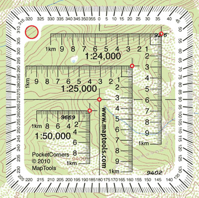 |
|
| ||
|
Triangle plotters A 1:24,000-scale triangular corner plotter is a triangular-shaped piece of transparent plastic that has two, one-kilometer measuring scales arranged with their zero-meter points abutting each other at a common, right angle corner. Triangular corner plotters are sometimes located in the interior of larger plotters, with access to the right-angle scales by way of a triangular-shaped cutout. |
A 1:24,000-scale UTM triangular corner plotter courtesy of MapTools. | 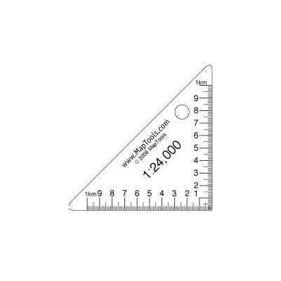 |
|
| ||
|
Slot plotters A 1:24,000-scale slot plotter is a rectangular piece of transparent plastic that has two, one-kilometer measuring scales arranged with their zero-meter points abutting each other at a common, right-angle, and a narrow slot cut along the entire length of one scale. |
A 1:24,000-scale UTM slot plotter — plus 360-degree compass rose — courtesy of MapTools. | 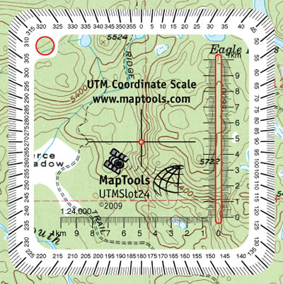 |
|
| ||
|
Grid overlays A 1:24,000-scale grid overlay is rectangular piece of transparent plastic with a one-kilometer by one-kilometer square on it, the interior of which contains a grid of nine top-to-bottom lines and nine side-to-side lines, all of which combine to form 100, hundred-by-hundred-meter squares. | A 1:24,000-scale UTM grid overlay — plus 360-degree compass rose — courtesy of MapTools. | 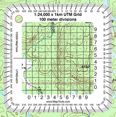 |
Field-expedient corner plotters
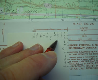 |
| A 1:24,000-scale, field-expedient,
UTM corner plotter made from a three-by-five-inch card, a pencil, and a quad's
marginal, bar scale. (Photo by Michael A. Neiger) |
An improvised, field-expedient roamer scale can be quickly and simply fashioned with a scrap of paper and a pencil.
Using the marginal kilometer/meter bar scale on a quadrangle, transfer one-kilometer's worth of 100-meter intervals to two edges of a piece of paper that meet at a common, right-angle corner.
Starting from the common corner, which would represent the zero point of both scales, number each hundred-meter tick mark with the numbers one through ten.
Corner plotters such as these can be handy with odd-scale maps as well as ones that have been reduced or enlarged during the photocopying process, which renders commonly-carried roamers useless.
Using a UTM corner plotter
The first step in calculating or plotting UTM coordinates on a quadrangle is to make sure the UTM plotter is the exact same scale as the quad. To do this, simply place one side of UTM plotter scale plotter against the kilometer bar scale in the map's margin to make sure one kilometer on the plotter matches one kilometer on the map.
When calculating or plotting UTM coordinates, keep in mind that easting coordinates are read from, and increase from, west to east, or left to right. Similarly, northing coordinates are read from, and increase from, south to north, or bottom to top.
Calculating
UTM coordinates
for a known position on a quadrangle
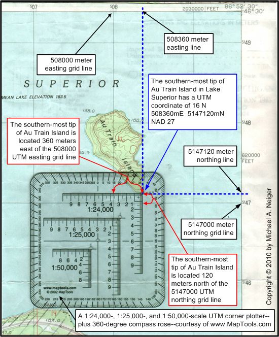 |
| A 1:24,000-scale MapTools
corner plotter showing how the UTM easting and northing coordinates are calculated
for the southern tip of Au Trail Island, Lake Superior, on a 1:24,000-scale, USGS,
Rock River, Michigan quadrangle. (Graphic by Michael A. Neiger) |
If you are trying to calculate UTM coordinates for a specific location on a quadrangle, simply place the zero-point of the corner plotter over the location in question — as show in the adjacent graphic — making sure the easting and northing plotter scales are aligned with west and south, respectively.
Once the UTM corner plotter is correctly positioned, simply add the easting plotter scale measurement between the location in question and the 1,000-meter easting grid line immediately to the west (360 meters in the graphic at right) with the value of this same 1,000-meter grid line (508000 meters in graphic at right) to calculate the location's easting grid coordinate (360 + 508000 = 508360 in graphic at right).
Next, add the northing plotter scale measurement between the location in question and the 1,000-meter northing grid line immediately to the south (120 meters in graphic at right) with the value of this same 1,000-meter grid line (5147000 in graphic at right) to calculate the location's northing grid coordinate (120 + 5147000 = 5147120 in graphic at right).
Note on missing marginal UTM grid lines: When you're plotting UTM coordinates near a quad's collar area — namely along the left and bottom margins — you may find an all-important easting or northing line, respectively, is missing. If so, simply measure backwards as needed from the nearest adjacent easting line to the east, or northing line to the north. Keep in mind that easting coordinates are read from, and increase from, west to east, or left to right, and northing coordinates are read from, and increase from, south to north, or bottom to top.
Plotting known UTM coordinates on a quadrangle
If you are trying to plot a known UTM coordinate on a quadrangle — say one derived from a GPS unit or given to you by a friend — first determine the 1,000-meter grid square the coordinate belongs in by comparing and contrasting the known easting and northing coordinate data strings with their corresponding labels along a quadrangle's marginal neat lines. At this point, you can disregard the last three digits of both the easting and northing coordinates, focusing just on the principal digits — the 1,000- and 10,000-meter digits — both of which are generally set in larger type along the neat lines and serve to identify the 1,000-meter grid squares.
Once you locate the 1,000-meter grid square that corresponds to the known UTM coordinate data string, place the zero point of the UTM corner plotter over the southwest corner of the 1,000-meter grid square — which is represented by the intersection of the westernmost easting boundary grid line and the southernmost northing boundary grid line — making sure the easting and northing plotter scales are aligned with west and south, respectively.The next step is to slide the UTM corner plotter eastward (right) until the westernmost easting boundary grid line is aligned with the appropriate sub-1,000-meter value of the known coordinate on the easting scale (360 meters in graphic above); and northward until the southernmost northing boundary grid line is aligned with the appropriate sub-1,000-meter value of the known coordinate on the nothing scale (120 meters in graphic above)
Vendors for UTM coordinate plotters
 | |
|
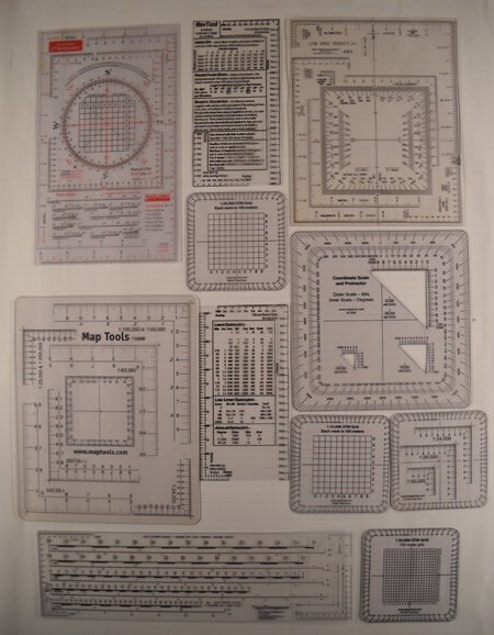
UTM roamer scales come in a wide variety of combinations,
formats, and sizes. (Photo by Michael A. Neiger) | |
Ben
Meadows Company
1-800-241-6401
Brooks-Range
Mountaineering Equipment Co.
1-718-585-1717
Brunton
Company
1-800-443-4871
See "map
quad tool"
Forestry
Suppliers, Inc.
1-800-647-5368
Lat.26Inc
1-800-305-0036
The
Map Store
1-877-921-6277
Map
Tools
1-650-529-9410
Mountains
Plus
1-877-411-4327
Ranger
Joe's
1-800-247-4541
Search
Gear
1-800-474-2612
Waypoint
Enterprises
1-888-412-2600
Top
UTM coordinates and map
datums
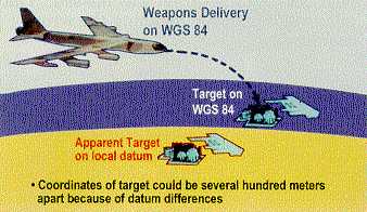
| Know your map datums! Correct map-datum selection is essential for team-level operational accuracy as well as joint interoperability among different agencies If you're a ground pounder coordinating with nautical and/or aerial assets — irrespective of whether you're using the LAT/LON or UTM coordinate system — keep in mind most current nautical and aeronautical charts are based on the NAD 83 (or WGS 84) map datum, not the NAD 27 datum common to most current USGS quadrangles. Map-datum selection or conversion errors are blamed for numerous friendly-fire accidents — some of the deadliest — in US conflicts such as the 1990-1991 Persian Gulf War (Desert Storm), the 2001-current War in Afghanistan (Operation Enduring Freedom), the 2003-current Iraq War (Operation Iraqi Freedom).
(Imagery courtesy of the US National Geospatial-Intelligence Agency)
|
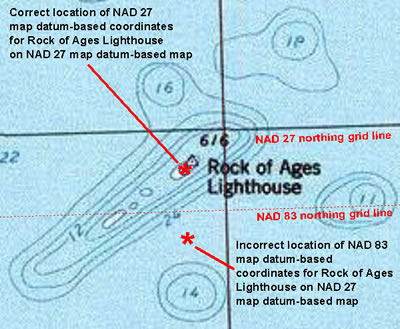 |
| A 207-meter northing
error is the result of using NAD 83 map datum-based coordinates for the Rock of
Ages Lighthouse on a NAD-27 map datum-based quadrangle. (Cartography by Michael A. Neiger) |
With hundreds of local, regional, national, and continental map datums in existence across the globe, it's essential that land navigators using the UTM coordinate system know what particular map datum is associated with every set of map coordinates — irrespective of whether they are latitude/longitude (LAT/LON) coordinates or universal transverse mercator (UTM) coordinates — obtained from quadrangles, global positioning system (GPS) units, or digital mapping software programs.
Map datum mismatches can result in significant errors in accuracy, up to 200 or 300 meters in the conterminous United States, and perhaps up to 1,600 meters in some regions of the world.
And datum shift is not constant — significant, systematic distortions occur over large areas.
The Rock of Ages Lighthouse just off the western tip of Lake Superior's Isle Royale offers a good example of the consequences of failing to account for different map datums.
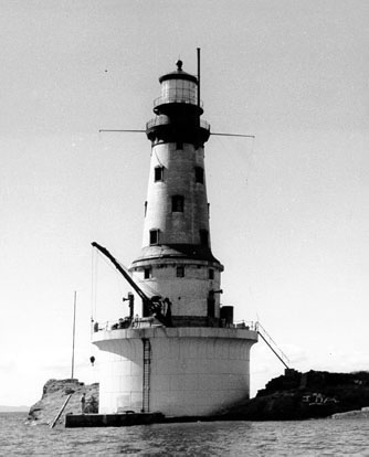
The Rock of Ages Lighthouse off the west end of Isle Royale in the northwestern
corner of Lake Superior.
(Photo courtesy of the United States Coast Guard)
When the lighthouse's NAD 83 coordinates are plotted on the USGS 1:24,000 Feldtmann Lake OEW, Michigan quadrangle — which is married to the NAD 27 map datum — the error is substantial, especially if navigation was taking place during a storm or foggy conditions.
While the easting coordinate error is nominal, only 2 meters, the northing coordinate error is more significant: 207 meters.
To learn more about map datums, click here.
Top
Coordinate format conversion
LAT/LON to UTM format converters
Montana State Library
Graphical Locator: XY-Data (DMS) Page
http://www.esg.montana.edu/gl/xy-data2.html
US
Department of Commerce
National Geodetic Survey
NGS Geodetic to UTM
Page
http://www.ngs.noaa.gov/cgi-bin/utm_getut.prl
GPSinformation.Net
More coordinate format converters
http://www.gpsinformation.net/
UTM to LAT/LON format converters
Montana State
Library
Graphical Locator: XY-Data (UTM) Page
http://www.esg.montana.edu/GL/xy-data3.html
US
Department of Commerce
National Geodetic Survey
NGS UTM to Geodetic
Page
http://www.ngs.noaa.gov/cgi-bin/utm_getgp.prl
GPSinformation.Net
More coordinate
format converters
http://www.gpsinformation.net/
Downloadable format conversion utilities
US Department of Commerce
National Geodetic Survey
NGS Geodetic Tool Kit Page
http://www.ngs.noaa.gov/TOOLS/
Offers UTM, LAT/LON, & USNG conversion utilities
National Geospatial-Intelligence
Agency
GeoTrans Translator
http://earth-info.nga.mil/GandG/geotrans/
GeoTrans utility converts wide array of coordinate formats
LAT/LON
& UTM coordinate
format conversion via a GPS unit
 A
Global Positioning System (GPS) unit can be used to convert latitude/longitude
coordinates to UTM coordinates, and vice versa.
A
Global Positioning System (GPS) unit can be used to convert latitude/longitude
coordinates to UTM coordinates, and vice versa.
Simply set the unit's coordinate format display (go to system setup menu) to the format of your coordinates and input your the coordinates. Next, change the coordinate format display of your GPS unit to the desired coordinate display format and all of the coordinates stored in your GPS unit will all be automatically converted to the new format.
LAT/LON
& UTM coordinate
format conversion via digital mapping software
 Digital
mapping software applications such as National Geographic's Topo! and MapTech's
Terrain Navigator can be used to convert latitude/longitude coordinates to UTM
coordinates, and vice versa.
Digital
mapping software applications such as National Geographic's Topo! and MapTech's
Terrain Navigator can be used to convert latitude/longitude coordinates to UTM
coordinates, and vice versa.
Simply set the coordinate format display of your mapping software to the format of your coordinates — visit the setup or preference's menu — and input your coordinates. Next, change the coordinate format display of your mapping software to the desired coordinate display format and all of the coordinates stored in the program will be converted automatically.
Top
Metric v. English distance
conversions
| 1 meter | = | 1.09 yards | |
| 100 meters | = | 109 yards | |
|
1,000 meters | = |
1,094 yards | |
Top
References
 |
| Map Use:
Reading, Analysis, and Interpretation,
7th edition, by Phillip C. Muehrcke and Juliana O. Muehrcke (Madison, Wisconsin:
JP Publications, 2011) |
Analytical and Computer Cartography, by Keith C. Clarke (Englewood Cliffs, New Jersey: Prentice Hall, 1990)
Applied Cartography: Source Materials for Mapmaking, by Thomas D. Rabenhorst and Paul D. McDermott (Columbus Ohio: Merrill Publishing Co., 1989)
ArcGIS 9: Understanding Map Projections, by Melita Kennedy (Redlands, California: Environmental Systems Research Institute [ESRI], 2004)
Basic GIS Coordinates, by Jan Van Sickle (Boca Raton, Florida: CRC Press LLC, 2004)
Basic Land Navigation (NFES 2865), by Mary Bogens, Michael Durfee, Lee Gardner, and Richard Streeper (Boise, Idaho: National Interagency Fire Center, Fire Training, 2007)
Coastlines: How Mapmakers Frame the World and Chart Environmental Change, by Mark Monmonier (Chicago, Illinois: University of Chicago Press, 2008)
Compass and Map Navigator: The Complete Guide to Staying Found, revised edition by Michael Hodgson (Guilford, Connecticut: The Globe Pequot Press, 2000)
The Complete Guide to Orienteering in North America: A Comprehensive Manual for the Outdoorsman, by Berndt Berglund (Toronto, Canada: Pagurian Press, 1979)
The Complete Idiot's Guide to Geocaching, by Jack W. Peter (Indianapolis, Indiana: Alpha Books, 2004)
A Comprehensive Guide to Land Navigation with GPS, third edition, by Noel J. Hotchkiss (Herndon, Virginia: Alexis Publishing, 1999)
Concepts and Techniques of Geographic Information Systems, by C. L. Lo and Albert K. W. Yeung (Upper Saddle River, New Jersey: Prentice Hall, 2002
Datums, Ellipsoids, Grids, and Grid Reference Systems (Defense Mapping Agency Technical Manual 8358.1), by John W. Hager, Larry L. Fry, Sandra S. Jacks, and David R. Hill (Fairfax, Virginian: Defense Mapping Agency Combat Support Center, 1990)
The Essential Wilderness Navigator: How to Find Your Way in the Great Outdoors, by David Seidman (Camden, Maine: Ragged Mountain Press, 1995)
Flattening the Earth: Two Thousand Years of Map Projections, by John P. Snyder (Chicago, Illinois: University of Chicago Press, 1993)
Fundamentals of Geographic Information Systems, fourth edition, by Michael N. Demers (Hoboken New Jersey: John Wiley and Sons, Inc., 2009)
Geodesy for the Layman (Defense Mapping Agency Technical Report 80-003), (St. Louis AFS, Missouri: Defense Mapping Agency Aerospace Center, 1983)
Geographic Information Systems Demystified, by Stephen R. Galati (Boston, Massachusetts: Artech House, 2006)
Geographic Information Systems for Geoscientists: Modeling with GIS, by Graeme F. Bonham-Carter (Tarrytown, New York: Elsevier Science Inc., 1994)
Getting Started With Geographic Information Systems, fourth edition, by Keith C. Clarke (Upper Saddle River, New Jersey: Prentice Hall, 2003)
GIS Data Conversion: Strategies, Techniques, and Management, Pat Hohl (Santa Fe, New Mexico, 1998)
GIS for Dummies, by Michael N. DeMers (Hoboken, New Jersey: Wiley Publishing, Inc., 2009)
GIS: The Geographic Language of Our Age, by Knut Grinderud, Haakon Rasmussen, Steinar Nilsen, Arvid Lillethun, Atle Holten, and Øystein Sanderud (Trondheim, Norway: Tapir Academic Press, 2009)
GPS for Dummies, by Joel McNamara (Indianapolis, Indiana: Wiley Publishing Inc., 2004)
The GPS Handbook: A Guide for the Outdoors, by Robert I. Egbert and Joseph E. King (Short Hills, New Jersey: Burford Books, 2003)
GPS Made Easy: Using Global Positioning Systems in the Outdoors, by Lawrence Letham (Seattle, Washington: The Mountaineers, 1998)
A GPS User Manual: Working With Garmin Receivers, by Dale DePriest (N.P., NP: 1st Books Library, 2003)
Integrated Geospatial Technologies: A Guide to GPS, GIS, and Data Logging, by Jeff Thurston, Thomas K. Poiker, and J. Patrick Moore (Hoboken, New Jersey: John Wiley and Sons, Inc., 2003
Introduction to Geographic Information Systems, fourth edition, by Kang-tsung Chang (New York, New York: McGraw Hill, 2008)
Land Navigation Handbook: The Sierra Club Guide to Map, Compass, and GPS, 2nd edition, by W. S. Kals, revised by Clyde Soles (San Francisco, California: Sierra Club Books, 2005)
The Language of Maps, by Philip J. Gersmehl (Indiana, Pennsylvania: National Council for Geographic Education, University of Pennsylvania, 1991)
Map Projections Used by the US Geological Survey, 2nd edition (Geological Survey Bulletin 1532), by John P. Snyder (Washington, D.C.: United States Government Printing Office, 1982)
Mapping, by David Greenhood, revised by Gerald L. Alexander (Chicago, Illinois: University of Chicago Press, 1964)
Maps and Compasses, second edition, by Percy W. Blandford (Blue Ridge Summit, Pennsylvania: Tab Books, 1992)
Mapping Hacks — Tips & Tools for Electronic Cartography, by Schuyler Erle, Rich Gibson, and Jo Walsh (Sebastopol, California: O'Reilly Media, Inc., 2005)
Map Reading and Land Navigation (FM 21-26), (Washington, DC: Department of the Army, 1993)
Map Reading and Land Navigation (FM 3-25.26), (Washington, DC: Department of the Army, 2001)
Map Use: Reading, Analysis, and Interpretation, 7th edition, by Phillip C. Muehrcke and Juliana O. Muehrcke (Madison, Wisconsin: JP Publications, 2011)
Map Use and Analysis, third edition, by John Campbell (Boston, Massachusetts: WCB/McGraw-Hill, 1998)
Measurements from Maps: Principle & Methods of Cartography, by D.H. Maling (Oxford England: Perganon Press, 1989)
Sniper Training and Employment (TC 23-14), (Washington, DC: Department of the Army, 1969)
Thinking About GIS: Geographic Information System Planning for Managers, by Roger Tomlinson (Redlands, California: ESRI Press, 2003)
The Universal Grids: Universal Transverse Mercator (UTM) and Universal Polar Stereographic (UPS) (Defense Mapping Agency Technical Manual 8358.2), by John W. Hager, James F. Behensky, and Brad W. Drew (Fairfax, Virginian: Defense Mapping Agency Combat Support Center, 1989)
The Universal Transverse Mercator (UTM) Grid (Fact Sheet 077-01), by the US Geological Survey (Reston, Virginia: US Geological Survey, 2001
Using GPS: GPS Simplified for Outdoor Adventures, by Bruce Grubbs (Falcon Publishing, Inc.: Helena, Montana, 1999)
Using the UTM Grid to Record Historic Sites, by Wilford P. Cole, US Department of the Interior (Washington, DC: US Government Printing Office, 1980)
UTM: Using your GPS with the Universal Transverse Mercator Coordinate System, third edition, by John Carnes (Woodside, California: MapTools, 2007)
Wilderness Navigation: Finding Your Way Using Map, Compass, Altimeter, and GPS, by Bob Burns and Mike Burns (Seattle, Washington: The Mountaineers, 1999)
Return to top of page :: Return to home page
In
God's wilderness
lies the hope of the world,
the great, fresh, unblighted,
unredeemed wilderness.
—
John Muir, 1838-1914
Alaska Wilderness, 1890
If
you've been able to read this Web page...
thank a Teacher;
If you've been
able to read this Web page in English...
thank a Veteran.
— Author
unknown
•
Copyright notice •
Content Copyright © 1984 —
November 28, 2022
by Michael A. Neiger
• All rights reserved •
No part of this Web page or this Web site protected by copyright law may be reproduced, transmitted, or used in any form — including graphic, electronic, Web, mechanical or other form — or by any means — including photocopying, recording, taping, Internet distribution, information storage retrieval system, or by other means — for any purpose, except by a reviewer, who may quote brief passages, without the prior, express, written permission of the author.
Comments?
Suggestions?
Dead links? Inaccurate info?
Contact the WebMaster,
Michael A. Neiger, at mneiger@hotmail.com
Web site URL: www.MibSAR.com
Return to top of page :: Return to home page
You're here: MiBSAR's home page :: SAR operations land navigation resource index page :: UTM coordinate system page